CHAPTER 3
THE WHEEL AND AXLE
CHAPTER LEARNING OBJECTIVES
Upon completion of this chapter, you should be able to do the following:
- Explain the advantage of the wheel and axle.
Have you ever tried to open a door when the knob was missing? If you have, you know that trying to twist that small four-sided shaft with your fingers is tough work. That gives you some appreciation of the advantage you get by using a knob. The doorknob is an example of a simple machine called a wheel and axle.
The steering wheel on an automobile, the handle of an ice cream freezer, and a brace and bit are all examples of a simple machine. All of these devices use the wheel and axle to multiply the force you exert. If you try to turn a screw with a screwdriver and it doesn’t turn, stick a screwdriver bit in the chuck of a brace. The screw will probably go in with little difficulty.
There’s something you’ll want to get straight right at the beginning. The wheel-and-axle machine consists of a wheel or crank rigidly attached to the axle, which turns with the wheel. Thus, the front wheel of an automobile is not a wheel-and-axle machine because the axle does not turn with the wheel.
MECHANICAL ADVANTAGE
How does the wheel-and-axle arrangement help to magnify the force you exert? Suppose you use a screwdriver bit in a brace to drive a stubborn screw. Look at figure 3-1, view A. You apply effort on the handle that moves in a circular path, the radius of which is 5 inches. If you apply a 10-pound force on the handle, how much force will you exert against the resistance at the screw? Assume the radius of the screwdriver blade is 1/4 inch. You are really using the brace as a second-class lever—see figure 3-1, view B. You can find the size of the resistance by using the formula
![]()
In that
L= radius of the circle through which the
1 = one-half the width of the edge of the screwdriver blade,
R= force of the resistance offered by the
E= force of effort applied on the handle.
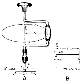
Figure 3-1.-It magnifies your effort.
Substituting in the formula and solving:
This means that the screwdriver blade will turn the screw with a force of 200 pounds. The relationship between the radius of the diameters or the circumferences of the wheel and axle tells you how much mechanical advantage you can get.
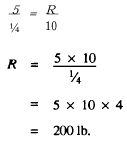
Take another situation. You raise the old oaken bucket, figure 3-2, using a wheel-and-axle arrangement. If the distance from the center of the axle to the handle is 8 inches and the radius of the drum around which the rope is wound is 2 inches, then you have a theoretical mechanical advantage of 4. That’s why these rigs were used.
MOMENT OF FORCE
In several situations you can use the wheel-and-axle to speed up motion. The rear-wheel sprocket of a bike, along with the rear wheel itself, is an example. When you are pedaling, the sprocket is attached to the wheel; so the combination is a true wheel-and-axle machine. Assume that the sprocket has a circumference of 8 inches, and the wheel circumference is 80 inches. If you turn the sprocket at a rate of one revolution per second, each sprocket tooth moves at a speed of 8 inches per
Figure 3-2.-The old oaken bucket.
second. Since the wheel makes one revolution for each revolution made by the sprocket, any point on the tire must move through a distance of 80 inches in 1 second. So, for every 8-inch movement of a point on the sprocket, you have moved a corresponding point on the wheel through 80 inches.
Since a complete revolution of the sprocket and wheel requires only 1 second, the speed of a point on the circumference of the wheel is 80 inches per second, or 10 times the speed of a tooth on the sprocket.
(NOTE: Both sprocket and wheel make the same number of revolutions per second, so the speed of turning for the two is the same.)
Here is an idea that you will find useful in under-standing the wheel and axle, as well as other machines. You probably have noticed that the force you apply to a lever starts to turn or rotate it about the fulcrum. You also know that a sheave on a fall starts to rotate the sheave of the block. Also when you turn the steering wheel of a car, it starts to rotate the steering column. Whenever you use a lever, or a wheel and axle, your effort on the lever arm or the rim of the wheel causes it to rotate about the fulcrum or the axle in one direction or another. If the rotation occurs in the same direction as the hands of a clock, we call that direction clockwise. If the rotation occurs in the opposite direction from that of the hands of a clock, we call that direction of rotation counterclockwise. A glance at figure 3-3 will make clear the meaning of these terms.
The force acting on the handle of a carpenter’s brace depends not only on the amount of that force, but also on the distance from the handle to the center of rotation. This is known as a moment of force, or a torque (pronounced tork). Moment of force and torque have the same meaning.
Look at the effect of the counterclockwise movement of the capstan bar in figure 3-4. Here the amount of the effort is designated El and the distance from the point where you apply the force to the center

Figure 3-3.-Directions of rotation.
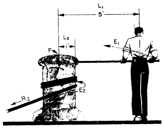
Figure 3-4.-Using the capstan.
of the axle is L1. Then, E1 x L1 is the moment of force. You’ll notice that this term includes both the amount of the effort and the distance from the point of application of effort to the center of the axle. Ordinarily, you measure the distance in feet and the applied force in pounds.
Therefore, you measure moments of force in foot-pounds (ft-lb). A moment of force is frequently called a moment.
By using a longer capstan bar, the sailor in figure 3-4 can increase the effectiveness of his push without making a bigger effort. If he applied his effort closer to the head of the capstan and used the same force, the moment of force would be less.
BALANCING MOMENTS
You know that the sailor in figure 3-4 would land flat on his face if the anchor hawser snapped. As long as nothing breaks, he must continue to push on the capstan bar. He is working against a clockwise moment of force that is equal in magnitude, but opposite in direction, to his counterclockwise moment of force. The resisting moment, like the effort moment, depends on two factors. In the case of resisting moment, these factors are the force (R2) with which the anchor pulls on the hawser and the distance (L2) from the center of the capstan to its rim. The existence of this resisting force would be clear if the sailor let go of the capstan bar. The weight of the anchor pulling on the capstan would cause the whole works to spin rapidly in a clockwise direction—and good-bye anchor! The principle involved here is that whenever the counterclockwise and the clockwise moments of force are in balance, the machine either moves at a steady speed or remains at rest.
This idea of the balance of moments of force can be summed up by the expression
![]()
Since a moment of force is the product of the amount of the force times the distance the force acts from the center of rotation, this expression of equality may be written
El x L1 = E2 x L2,
in that
EI = force of effort,
L1 = distance from fulcrum or axle to point where you apply force,
E2 = force of resistance, and
L2= distance from fulcrum or center axle to the point where you apply resistance.
EXAMPLE 1
Put this formula to work on a capstan problem. You grip a single capstan bar 5 feet from the center of a capstan head with a radius of 1 foot. You have to lift a 1/2-ton anchor. How big of a push does the sailor have to exert?
First, write down the formula
El x L1 = E2 x L2,
Here
L1=5
E2 = 1,000 pounds, and
L2=l.
Substitute these values in the formula, and it becomes:
E1 X 5 = 1,000 x 1
and
![]() = 200 pounds
= 200 pounds
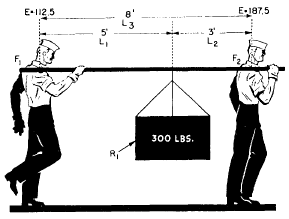
Figure 3-5.-A practical application.
Example 2
Consider now the sad case of Slim and Sam, as illustrated in figure 3-5. Slim has suggested that they carry the 300-pound crate slung on a handy 10-foot pole. He was smart enough to slide the load up 3 feet from Sam’s shoulder.
Here’s how they made out. Use Slim’s shoulder as a fulcrum (Fl). Look at the clockwise movement caused by the 300-pound load. That load is 5 feet away from Slim’s shoulder. If RI is the load, and Ll the distance from Slim’s shoulder to the load, the clockwise moment (MA) is
MA = R1 x Ll = 300 x 5 = 1,500 ft-lb.
With Slim’s shoulder still acting as the fulcrum, the resistance of Sam’s effort causes a counterclockwise moment (MB) acting against the load moment. This counterclockwise moment is equal to Sam’s effort (E2) times the distance (L3) from his shoulder to the fulcrum (F1) at Slim’s shoulder. Since L2 = 8 ft, the formula is
MB = E2 x L3 = E2 X 8 = 8E2
There is no rotation, so the clockwise moment and the counterclockwise moment are equal. MA = MB.
Hence
1,500 = 8E2
![]() = 187.5 pounds.
= 187.5 pounds.
So poor Sam is carrying 187.5 pounds of the 330-pound load.
What is Slim carrying? The difference between 300 and 187.5 = 112.5 pounds, of course! You can check your answer by the following procedure.
This time, use Sam’s shoulder as the fulcrum (F2). The counterclockwise moment (Mc) is equal to the 300-pound load (Rl) times the distance (b = 3 feet) from Sam’s shoulder. Mc 300 x 3 = 900 foot-pounds. The clockwise moment (mD) is the result of Slim’s lift (EI) acting at a distance (L3) from the fulcrum. L3 = 8 feet. Again, since counterclockwise moment equals clock-wise moment, you have
900 = E1 X 8
Figure 3-6.-A couple.
Figure 3-7.-Valves.
and
![]()
Slim, the smart sailor, has to lift only 112.5 pounds. There’s a sailor who really puts his knowledge to work.
THE COUPLE
Take a look at figure 3-6. It’s another capstan-turning situation. To increase an effective effort, place a second capstan bar opposite the first and another sailor can apply a force on the second bar. The two sailors in figure 3-6 will apparently be pushing in opposite directions. Since they are on opposite sides of the axle, they are actually causing rotation in the same direction. If the two sailors are pushing with equal force, the moment of force is twice as great as if only one sailor were pushing. This arrangement is known technically as a couple.
You will see that the couple is a special example of the wheel and axle. The moment of force is equal to the product of the total distance (Ln between the two points and the force (E1) applied by one sailor. The equation for the couple may be written
E1 x L1 = E2 x L2
APPLICATIONS AFLOAT AND ASHORE
A trip to the engine room important the wheel and axle makes you realize how is on the modern ship.
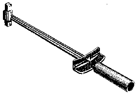
Figure 3-8.—A simple torque wrench.
Everywhere you look you see wheels of all sizes and shapes. We use most of them to open and close valves quickly. One common type of valve is shown in figure 3-7. Turning the wheel causes the threaded stem to rise and open the valve. Since the valve must close watertight, airtight, or steamtight, all the parts must fit snugly. To move the stem on most valves without the aid of the wheel would be impossible. The wheel gives you the necessary mechanical advantage.
You’ve handled enough wrenches to know that the longer the handle, the tighter you can turn a nut. Actually, a wrench is a wheel-and-axle machine. You can consider the handle as one spoke of a wheel and the place where you take hold of the handle as a point on the rim. You can compare the nut that holds in the jaws of the wrench to the axle.
You know that you can turn a nut too tight and strip the threads or cause internal parts to seize. This is especially true when you are taking up on bearings. To make the proper adjustment, you use a torque wrench. There are several types. Figure 3-8 shows you one that is very simple. When you pull on the handle, its shaft bends. The rod fixed on the pointer does not bend. The pointer shows on the scale the torque, or moment of force, that you are exerting. The scale indicates pounds, although it is really measuring foot-pounds to torque. If the nut is to be tightened by a moment of 90 ft-1b, you pull until the pointer is opposite the number 90 on the scale. The servicing or repair manual on an engine or piece of machinery tells you what the torque—or moment of force—should be on each set of nuts or bolt.
The gun pointer uses a couple to elevate and depress the gun barrel. He cranks away at a handwheel that has two handles. The right-hand handle is on the opposite side of the axle from the left-hand handle—180° apart.
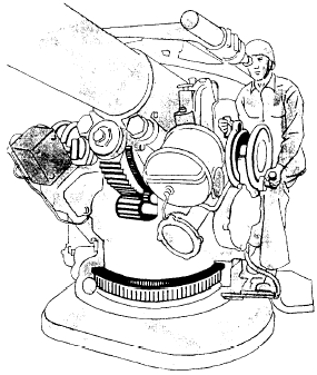
Figure 3-9.-A pointer’s handwheel.
Look at figure 3-9. When this gun pointer pulls on one handle and pushes on the other, he’s producing a couple. If he cranks only with his right hand, he no longer has a couple—just a simple first-class lever! And he’d have to push twice as hard with one hand.
A system of gears-a gear train-transmits the motion to the barrel. A look at figure 3-10 will help you to figure the forces involved. The radius of the wheel is 6 inches—1/2 foot-and turns each handle with a force of 20 pounds. The moment on the top that rotates the wheel in a clockwise direction is equal to 20 x 1/2 = 10 ft-lb. The bottom handle also rotates the wheel in the same direction with an equal moment. Thus, the total twist or torque on the wheel is 10 + 10 = 20 ft-lb. To get the same moment with one hand, apply a 20-pound force. The radius of the wheel would have to be twice as much—12 inches—or one foot. The couple is a convenient arrangement of the wheel-and-axle machine.
SUMMARY
Here is a quick review of the wheel and axle-facts you should have straight in your mind:
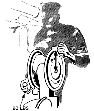
Figure 3-10.-Developing a torque.
A wheel-and-axle machine has the wheel fixed rigidly to the axle. The wheel and the axle turn together.
Use the wheel and axle to magnify your effort or to speed it up.
You call the effect of a force rotating an object around an axis or fulcrum a moment of force, or simply a moment.
When an object is at rest or is moving steadily, the clockwise moments are just equal and opposite to the counterclockwise moments.
Moments of force depend upon two factors: (1) the amount of the force and (2) the distance from the fulcrum or axis to the point where the force is applied.
When you apply two equal forces at equal distances on opposite sides of a fulcrum and move those forces in opposite directions so they both tend to cause rotation about the fulcrum, you have a couple.

Tidak ada komentar:
Posting Komentar