CHAPTER 1
LEVERS
CHAPTER LEARNING OBJECTIVES
Upon completion of this chapter, you should be able to do the following:
Through the ages, ships have evolved from crude rafts to the huge complex cruisers and carriers of today’s Navy. It was a long step from oars to sails, another long step from sails to steam, and another long step to today’s nuclear power. Each step in the progress of shipbuilding has involved the use of more and more machines.
Today’s Navy personnel are specialists in operating and maintaining machinery. Boatswains operate winches to hoist cargo and the anchor; personnel in the engine room operate pumps, valves, generators, and other machines to produce and control the ship’s power; personnel in the weapons department operate shell hoists and rammers and elevate and train the guns and missile launchers; the cooks operate mixers and can openers; personnel in the CB ratings drive trucks and operate cranes, graders, and bulldozers. In fact, every rating in the Navy uses machinery sometime during the day’s work.
Each machine used aboard ship has made the physical work load of the crew lighter; you don’t walk the capstan to raise the anchor, or heave on a line to sling cargo aboard. Machines are your friends. They have taken much of the backache and drudgery out of a sailor’s lift. Reading this book should help you recognize and understand the operation of many of the machines you see about you.
WHAT IS A MACHINE?
As you look about you, you probably see half a dozen machines that you don’t recognize as such. Ordinarily you think of a machine as a complex device-a gasoline engine or a typewriter. They are machines; but so are a hammer, a screwdriver, a ship’s wheel. A machine is any device that helps you to do work. It may help by changing the amount of force or the speed of action. A claw hammer, for example, is a machine. You can use it to apply a large force for pulling out a nail; a relatively small pull on the handle produces a much greater force at the claws.
We use machines to transform energy. For example, transfer energy from one place to another. For example, the connecting rods, crankshaft, drive shaft, and rear axle of an automobile transfer energy from the engine to the rear wheels.
Another use of machines is to multiply force. We use a system of pulleys (a chain hoist, for example) to lift a heavy load. The pulley system enables us to raise the load by exerting a force that is smaller than the weight of the load. We must exert this force over a greater distance than the height through which the load is raised; thus, the load will move slower than the chain on which we pull. The machine enables us to gain force, but only at the expense of speed.
Machines may also be used to multiply speed. The best example of this is the bicycle, by which we gain speed by exerting a greater force.
Machines are also used to change the direction of a force. For example, the Signalman’s halyard enables one end of the line to exert an upward force on a signal flag while a downward force is exerted on the other end.
There are only six simple machines: the lever, the block, the wheel and axle, the inclined plane, the screw, and the gear. Physicists, however, recognize only two basic principles in machines: those of the lever and the inclined plane. The wheel and axle, block and tackle, and gears may be considered levers. The wedge and the screw use the principle of the inclined plane.
When you are familiar with the principles of these simple machines, you can readily understand the
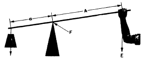
Figure 1-1.-A simple lever.
operation of complex machines. Complex machines are merely combinations of two or more simple machines.
THE LEVER
The simplest machine, and perhaps the one with which you are most familiar, is the lever. A seesaw is a familiar example of a lever in which one weight balances the other.
You will find that all levers have three basic parts: the fulcrum (F), a force or effort (E), and a resistance (R). Look at the lever in figure 1-1. You see the pivotal point (fulcrum) (F); the effort (E), which is applied at a distance (A) from the fulcrum; and a resistance (R), which acts at a distance (a) from the fulcrum. Distances A and a are the arms of the lever.
CLASSES OF LEVERS
The three classes of levers are shown in figure 1-2. The location of the fulcrum (the fixed or pivot point) in relation to the resistance (or weight) and the effort determines the lever class.
First Class
In the first class (fig. 1-2, part A), the fulcrum is located between the effort and the resistance. As mentioned earlier, the seesaw is a good example of a first-class lever. The amount of weight and the distance from the fulcrum can be varied to suit the need.
Notice that the sailor in figure 1-3 applies effort on the handles of the oars. An oar is another good example. The oarlock is the fulcrum, and the water is the resistance. In this case, as in figure 1-1, the force is applied on one side of the fulcrum and the resistance to be overcome is applied to the opposite side; hence, this is a first class lever. Crowbars, shears, and pliers are common examples of this class of levers.
Second Class
The second class of lever (fig. 1-2, part B) has the fulcrum at one end, the effort applied at the other end, and the resistance somewhere between those points. The
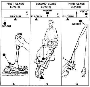
Figure 1-2.-Three classes of levers.
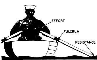
Figure 1-3.-Oars are levers.
wheelbarrow in figure 1-4 is a good example of a second-class lever. If you apply 50 pounds of effort to the handles of a wheelbarrow 4 feet from the fulcrum (wheel), you can lift 200 pounds of weight 1 foot from the fulcrum. If the load were placed farther away from the wheel, would it be easier or harder to lift?
Levers of the first and second class are commonly used to help in overcoming big resistances with a relatively small effort.
Third Class
Sometimes you will want to speed up the movement of the resistance even though you have to use a large amount of effort. Levers that help you accomplish this are in the third class of levers. As shown in figure 1-2, part C, the fulcrum is at one end of the lever, and the
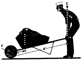
Figure 1-4.-This makes it easier.
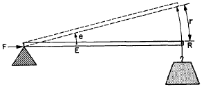
Figure 1-5.-A third-class lever.
weight or resistance to be overcome is at the other end, with the effort applied at some point between. You can always spot the third-class levers because you will find the effort applied between the fulcrum and the
resistance. Look at figure 1-5. It is easy to see that while E moved the short distance (e), the resistance (R) was moved a greater distance (r). The speed of R must have been greater than that of E, since R covered a greater distance in the same length of time.
Your arm (fig. 1-6) is a third-class lever. It is this lever action that makes it possible for you to flex your arms so quickly. Your elbow is the fulcrum. Your biceps muscle, which ties onto your forearm about an inch below the elbow, applies the effort; your hand is the resistance, located about 18 inches from the fulcrum. In the split second it takes your biceps muscle to contract an inch, your hand has moved through an 18-inch arc. You know from experience that it takes a big pull at E to overcome a relatively small resistance at R. Just to experience this principle, try closing a door by pushing on it about 3 or 4 inches from the hinges (fulcrum). The moral is, you don’t use third-class levers to do heavy jobs; you use them to gain speed.
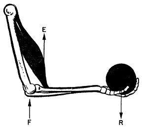
Figure 1-6.-Your arm is a lever.
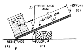
Figure 1-7.-Easy does it.
One convenience of machines is that you can determine in advance the forces required for their operation, as well as the forces they will exert. Consider for a moment the first class of levers. Suppose you have an iron bar, like the one shown in figure 1-7. This bar is 9 feet long, and you want to use it to raise a 300-pound crate off the deck while you slide a dolly under the crate; but you can exert only 100 pounds to lift the crate. So, you place the fulcrum-a wooden block-beneath one end of the bar and force that end of the bar under the crate. Then, you push down on the other end of the bar. After a few adjustments of the position of the fulcrum, you will find that your 100-pound force will just fit the crate when the fulcrum is 2 feet from the center of the crate. That leaves a 6-foot length of bar from the fulcrum to the point where you pushdown. The 6-foot portion is three times as long as the distance from the fulcrum to the center of the crate. And you lifted a load three times as great as the force you applied (3 x 100 = 300 pounds).
Here is a sign of a direct relationship between the length of the lever arm and the force acting on that arm.
You can state this relationship in general terms by saying: the length of the effort arm is the same number of times greater than the length of the resistance arm as the resistance to be overcome is greater than the effort you must apply. Writing these words as a mathematical equation, we have
![]()
where
L = length of effort arm,
l = length of resistance arm,
R = resistance weight or force, and
E= effort force.
Remember that all distances must be in the same units, such as feet, and that all forces must be in the same units, such as pounds.
Now let’s take another problem and see how it works out. Suppose you want to pry up the lid of a paint can (fig. 1-8) with a 6-inch file scraper, and you know that the average force holding the lid is 50 pounds. If the distance from the edge of the paint can to the edge of the cover is 1 inch, what force will you have to apply on the end of the file scraper?
According to the formula,
![]()
here,
L = 5 inches
l = 1 inch
R = 50 pounds, and
E is unknown.
Then, substituting the numbers in their proper places, we have
![]()
and
![]() = 10 pounds
= 10 pounds
You will need to apply a force of only 10 pounds.
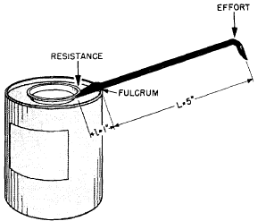
Figure 1-8.-A first-class job.
The same general formula applies for the second class of levers; but you must be careful to measure the proper lengths of the effort arm and the resistance arm. Looking back at the wheelbarrow problem, assume that the length of the handles from the axle of the wheel—which is the fulcrum-to the grip is 4 feet. How long is the effort arm? You’re right, it’s 4 feet. If the center of the load of sand is 1 foot from the axle, then the length of the resistance arm is 1 foot.
By substituting in the formula,

and
E = 50 pounds.
Now for the third-class lever. With one hand, you lift a projectile weighing approximately 10 pounds. If your biceps muscle attaches to your forearm 1 inch below your elbow and the distance from the elbow to the palm of your hand is 18 inches, what pull must your muscle exert to hold the projectile and flex your arm at the elbow?
By substituting in the formula,
![]()
it becomes
![]()
and
E = 18 x 10 = 180 pounds.
Your muscle must exert a 180-pound pull to hold up a 10-pound projectile. Our muscles are poorly arranged for lifting or pulling-and that’s why some work seems pretty tough. But remember, third-class levers are used primarily to speed up the motion of the resistance.
Curved Lever Arms
Up to this point, you have been looking at levers with straight arms. In every case, the direction in which the resistance acts is parallel to the direction in which the effort is exerted. However, not all levers are straight. You ’ll need to learn to recognize all types of levers and to understand their operation.
Look at figure 1-9. You may wonder how to measure the length of the effort arm, which is represented by the curved pump handle. You do not measure around the curve; you still use a straight-line distance. To determine the length of the effort arm, draw a straight line (AB) through the point where the effort is applied and in the direction that it is applied. From point E on this line, draw a second line (EF) that passes through the fulcrum and is perpendicular to line AB. The length of line EF is the actual length (L) of the effort arm.
To find the length of the resistance arm, use the same method. Draw a line (MN) in the direction that the resistance is operating and through the point where the resistance is attached to the other end of the handle. From point R on this line, draw a line (RF) perpendicular to MN so that it passes through the fulcrum. The length of RF is the length (l) of the resistance arm.
Regardless of the curvature of the handle, this method can be used to find lengths L and l. Then, curved levers are solved just like straight levers.
MECHANICAL ADVANTAGE
There is another thing about the first and second classes of levers that you have probably noticed by now. Since they can be used to magnify the applied force, they provide positive mechanical advantages. The third-class lever provides what is called a fractional mechanical advantage, which is really a mechanical disadvantage— you use more force than the force of the load you lift. In the wheelbarrow problem, you saw that a 50-pound pull actually overcame the 200-pound weight
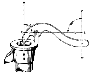
Figure 1-9.-A curved lever arm.
of the sand. The sailor’s effort was magnified four times, so you may say that the mechanical advantage of the wheelbarrow is 4. Expressing the same idea in mathematical terms,
MECHANICAL ADVANTAGE = ![]()
or
![]()
Thus, in the case of the wheelbarrow,
![]()
This rule—mechanical advantage equals resistance divided by effort —applies to all machines.
The mechanical advantage of a lever may also be found by dividing the length of effort arm A by the length of resistance arm a. Stated as a formula, this reads:
![]()
or
![]()
How does this apply to third-class levers? Your muscle pulls with a force of 1,800 pounds to lift a 100-pound projectile. So you have a mechanical advantage of
![]()
which is fractional-less than 1.
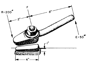
Figure 1-10.-It’s a dog.
APPLICATIONS AFLOAT AND ASHORE
Doors, called hatches aboard a ship, are locked shut by lugs called dogs. Figure 1-10 shows you how these dogs are used to secure the door. If the handle is four times as long as the lug, that 50-pound heave of yours is multiplied to 200 pounds against the slanting face of the wedge. Incidentally, take a look at the wedge—it’s an inclined plane, and it multiplies the 200-pound force by about 4. Result: Your 50-pound heave actually ends up as a 800-pound force on each wedge to keep the hatch closed! The hatch dog is one use of a first-class lever in combination with an inclined plane.
The breech of a big gun is closed with a breech plug. Figure 1-11 shows you that this plug has some interrupted screw threads on it, which fit into similar
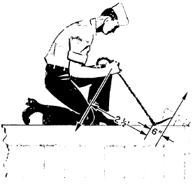
Figure 1-12.-Using a wrecking bar.
interrupted threads in the breech. Turning the plug part way around locks it into the breech. The plug is locked and unlocked by the operating lever. Notice that the connecting rod is secured to the operating lever a few inches from the fulcrum. You’ll see that this is an application of a second-class lever.
You know that the plug is in there good and tight. But, with a mechanical advantage of 10, your 100-pound pull on the handle will twist the plug loose with a force of a half ton.
If you’ve spent any time opening crates at a base, you’ve already used a wrecking bar. The sailor in figure 1-12 is busily engaged in tearing that crate open.
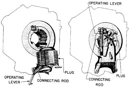
Figure 1-11.-The breech of an 8-inch gun.

Figure 1-13.-An electric crane.
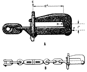
Figure 1-14.-A. A pelican hook; B. A chain stopper.
The wrecking bar is a first-class lever. Notice that it has curved lever arms. Can you figure the mechanical advantage of this one? Your answer should be M.A. = 5.
The crane in figure 1-13 is used for handling relatively light loads around a warehouse or a dock. You can see that the crane is rigged as a third-class lever; the effort is applied between the fulcrum and the load. This gives a mechanical advantage of less than 1. If it’s going to support that 1/2-ton load, you know that the pull on the lifting cable will have to be considerably greater than 1,000 pounds. How much greater? Use the formula to figure it out:
![]()
Got the answer? Right. . . E = 1,333 pounds
Now, because the cable is pulling at an angle of E, you can use some trigonometry to find that the pull on the cable will be about 3,560 pounds to lift the 1/2-ton weight! However, since the loads are
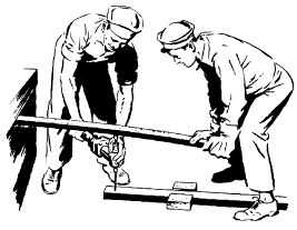
Figure 1-15.-An improvised drill press.
generally light, and speed is important, the crane is a practical and useful machine.
Anchors are usually housed in the hawsepipe and secured by a chain stopper. The chain stopper consists of a short length of chain containing a turnbuckle and a pelican hook. When you secure one end of the stopper to a pad eye in the deck and lock the pelican hook over the anchor chain, the winch is relieved of the strain.
Figure 1-14, part A, gives you the details of the pelican hook. Figure 1-14, part B, shows the chain stopper as a whole. Notice that the load is applied close to the fulcrum. The resistance arm is very short. The bale shackle, which holds the hook secure, exerts its force at a considerable distance from the fulcrum. If the chain rests against the hook 1 inch from the fulcrum and the bale shackle is holding the hook closed 12 + 1 = 13 inches from the fulcrum, what’s the mechanical advantage? It’s 13. A strain of only 1,000 pounds on the base shackle can hold the hook closed when a 6 1/2-ton anchor is dangling over the ship’s side. You’ll recognize the pelican hook as a second-class lever with curved arms.
Figure 1-15 shows you a couple of guys who are using their heads to spare their muscles. Rather than exert themselves by bearing down on that drill, they pick up a board from a nearby crate and use it as a second-class lever.
If the drill is placed halfway along the board, they will get a mechanical advantage of 2. How would you increase the mechanical advantage if you were using this rig? Right. You would move the drill in closer to the fulcrum. In the Navy, a knowledge of levers and how to apply them pays off.
SUMMARY
Now for a brief summary of levers:
Levers are machines because they help you to do your work. They help by changing the size, direction, or speed of the force you apply.
There are three classes of levers. They differ primarily in the relative points where effort is applied, where the resistance is overcome, and where the fulcrum is located.
First-class levers have the effort and the resistance on opposite sides of the fulcrum, and effort and resistance move in opposite directions.
Second-class levers have the effort and the resistance on the same side of the fulcrum but the effort is farther from the fulcrum than is the resistance. Both effort and resistance move in the same direction.
Third-class levers have the effort applied on the same side of the fulcrum as the resistance but the effort is applied between the resistance and the fulcrum, and both effort and resistance move in the same direction.
First- and second-class levers magnify the amount of effort exerted and decrease the speed of effort. First-class and third-class levers magnify the distance and the speed of the effort exerted and decrease its magnitude.
The same general formula applies to all three types of levers:
![]()
Mechanical advantage (M.A.) is an expression of the ratio of the applied force and the resistance. It may be written:
![]()

Tidak ada komentar:
Posting Komentar